If you have comments, questions or interest in the technology described in the following article, please contact us at:
Email: cometrue@icometrue.com
Field-Programmable Multi-Chip Package (FPMCP)
Abiding by the Moore’s Law, the advanced semiconductor chip technology provides chips with high circuit density, high operation frequency, high computing speed and low power consumption; while on the other hand, in the “More-than-Moore” approach, the advanced packaging technology provides heterogeneous integration to include multiple chips fabricated by different technology nodes (for example: 5 nm, 7 nm, 10 nm or less advanced than 10 nm) or multiple chips having different functions (such as CPU, GPU, ASIC, SOC, PMIC, FPGA, SRAM, DRAM, Flash, MRAM…, etc.) in a single package made by advanced multi-chip packaging technologies (such as Si-interposer-based package, Fan-Out package and 3D stacking package).
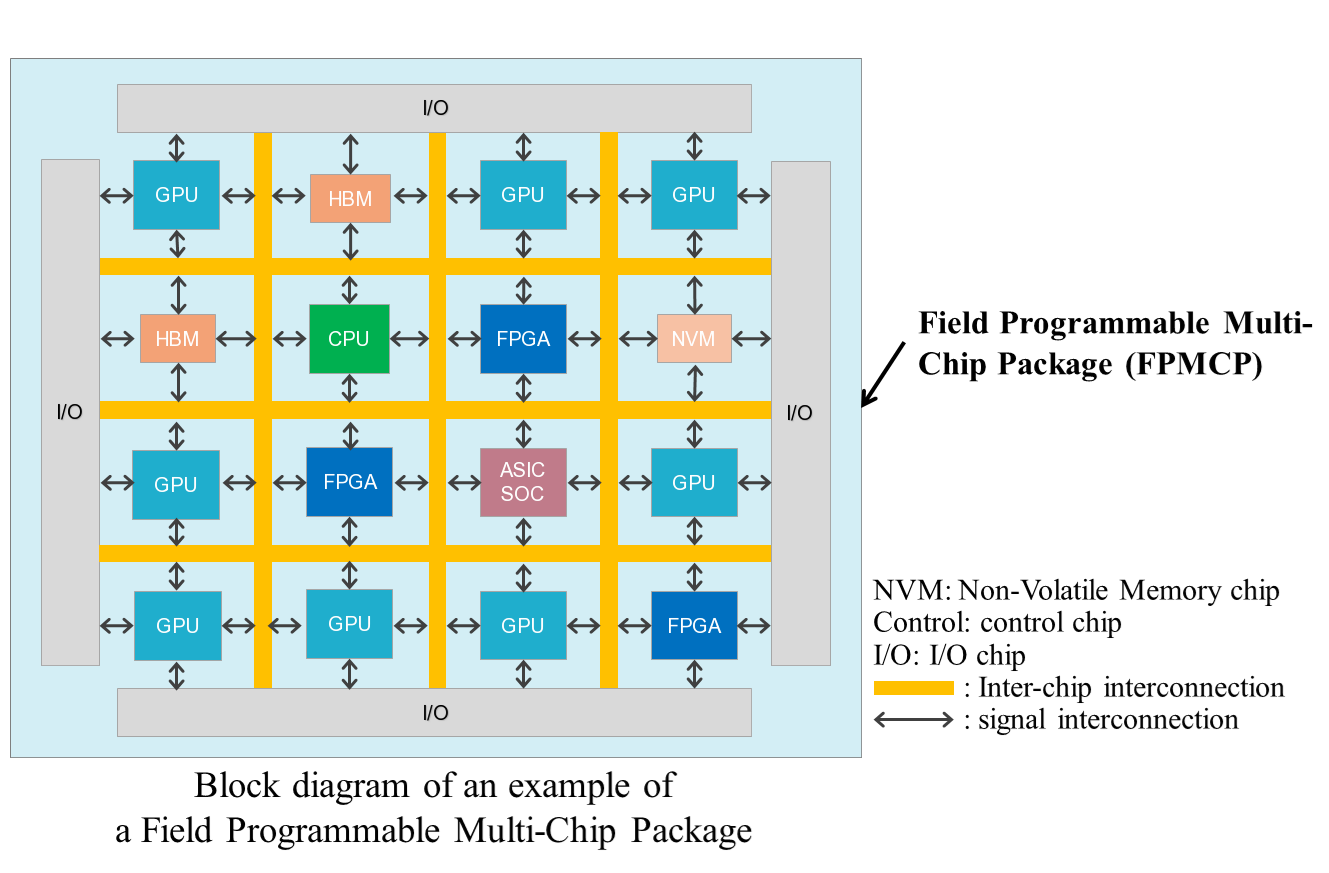
Combining the semiconductor IC chip technology abiding by Moore’s law and the advanced packaging technology based on More-than-Moore approach mentioned above, iCometrue proposed, in 2016, a concept of FPMCP (Field-Programmable Multi-Chip Package). FPMCP is formed by packaging one or more FPGA chips, a Non-Volatile Memory (NVM) chip, one or more logic computing chips (for example: CPU, GPU, ASIC, SOC…, etc.) and one or more auxiliary chips (for example: I/O chip, control chip, PMIC…, etc.) in a single package by using the advanced multi-chip packaging technologies. Through configuring or re-configuring the FPGA chip in the FPMCP, the FPGA chip could work with the other chips in the same package to provide various functions, therefore, increase the application flexibility of the multi-chip package, and turns the FPMCP into an Application Specific Multi-Chip Package (ASMCP) for specific applications.
The FPGA in the FPMCP is used for defining or changing the functions and applications of the FPMCP, and for cooperating with the other computing chips in the FPMCP to accelerate the computing speed of these chips.
With the NVM chip packaged in the FPMCP, the configuration data or information of the FPGA chip could be stored in the non-volatile memory cells of the NVM chip. By including the NVM and FPGA chips in it, the FPMCP becomes non-volatile field-programmable, and turns into a non-volatile ASMCP for specific applications.
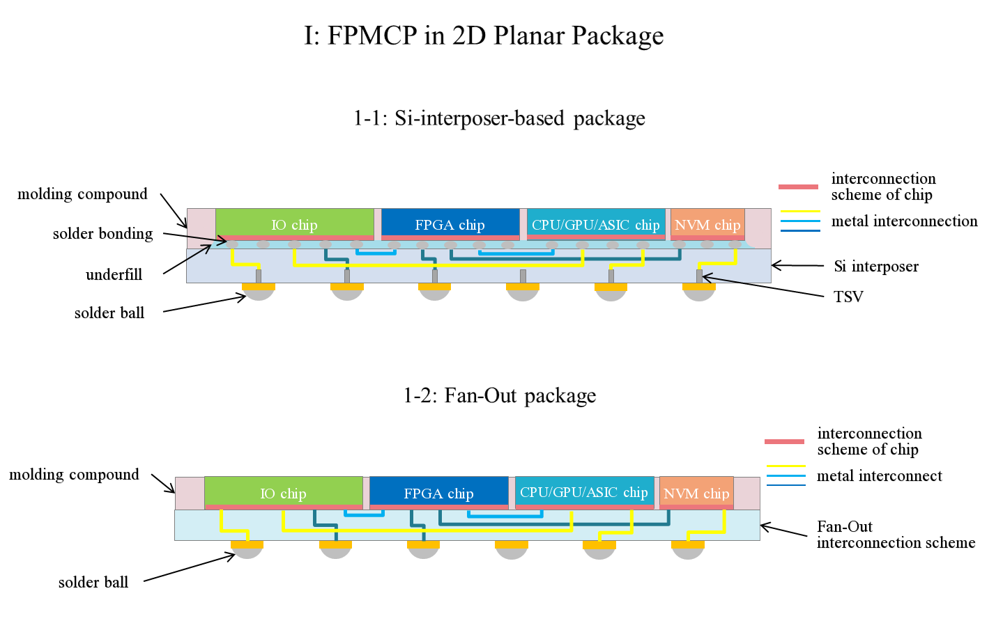
The schematic planar drawing of an example of FPMCP is shown below:
(I) The FPGA chip turns the MCP into the field-programmable MCP (FPMCP)
The purposes of including the FPGA chip in the FPMCP are detailed below:
(A) Define or change the function/application of the FPMCP by configuring or re-configuring the FPGA chip
The FPGA chip defines or changes the function/application of the FPMCP through the following four methods:
(i) Define or change the function of the FPGA chip to define or change the function/application of the FPMCP
The FPGA chip in the FPMCP could be configured or re-configured for different functions/applications. For example, the FPGA chip is configured or re-configured as a MCU (Micro-Controller Unit) chip and then the FPMCP is used in smart cars, robots or various applications in industry; or the FPGA chip is configured or re-configured as a DSP (Digital Signal Processor) chip and then the FPMCP is used in the application of multimedia, cloud data center and smart network.
(ii) Use the FPGA chip to define or change the inter-chip interconnection between the chips or the on-chip interconnection on a chip in the FPMCP for different functions/applications
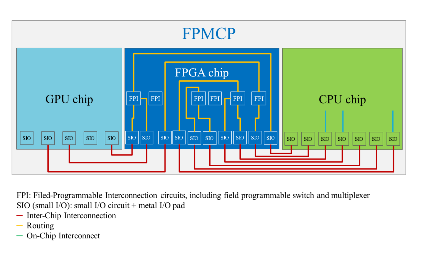
The Field-Programmable Interconnection Circuits (FPI Circuits, comprising field programmable switches and multiplexers) of the FPGA chip could be configured or re-configured to change the inter-chip interconnection between the chips (FPGA chips, other logic computing chips, auxiliary chips) in the FPMCP and, therefore, change the function/application of the FPMCP.
The FPI circuit on the FPGA chip is used for:
(a) Configuring or reconfiguring the inter-chip interconnection between two chips in the FPMCP. For a first example, the FPI circuit (comprising a switch configurable by a memory cell) controls, in accordance with data stored in the memory cell of the FPI circuit, the connection between CPU and GPU chips. For a second example, the SIO (small I/O) on the CPU chip couples, in accordance with the selection of the FPI circuit (comprising a multiplexer and switch each configurable by a memory cell) based on data stored in the memory cells of the FPI circuit, to one of the plurality of SIOs on the GPU chip.
(b) Configuring or reconfiguring the on-chip interconnection on a chip in the FPMCP. For a first example, the FPI circuit (comprising a switch configurable by a memory cell) controls, in accordance with data stored in the memory cell of the FPI circuit, the connection between first and second interconnects on the CPU chip. For a second example, the first interconnect on the CPU chip couples, in accordance with the selection of the FPI circuit (comprising a multiplexer and switch each configurable by a memory cell) based on data stored in the memory cells of the FPI circuit, to one of second and third interconnects on the CPU chip.
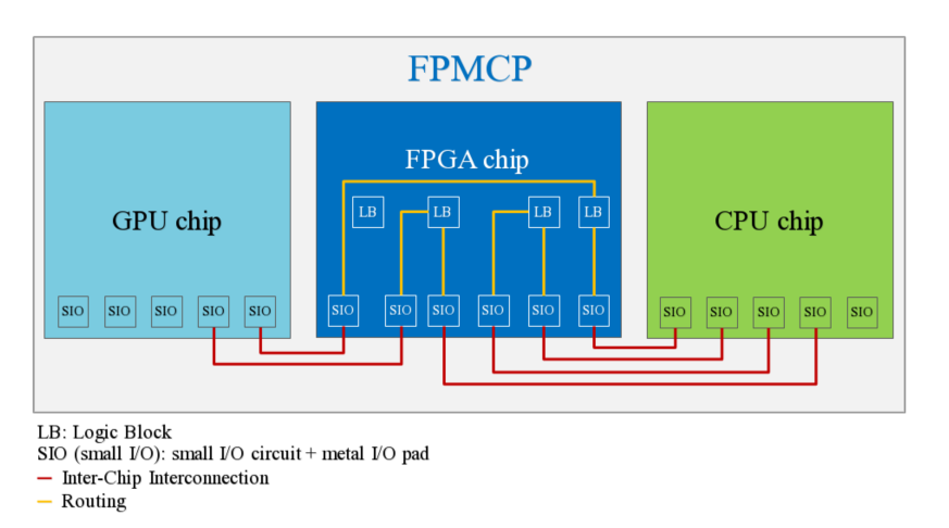
The schematic drawing below shows how the FPI circuits on the FPGA chip configure or reconfigure the inter-chip interconnection between the CPU and GPU chips and the on-chip interconnection on the CPU chip in the FPMCP:
(iii) Use the FPGA chip to define or change the cooperating operations between the FPGA chip and the other chips in the FPMCP for different functions/applications
The chips (logic computing chips, auxiliary chips, etc.) in the FPMCP could be operated in cooperation with each other via the configured LBs (Logic Block) of FPGA chip. The LBs comprise logic cells (or logic elements) and can be configured or re-configured for logic operations. By configuring or re-configuring the LBs of the FPGA chip, it turns the FPMCP into an ASMCP for specific applications. For example, a signal is delivered from Chip A (a chip in the FPMCP) to the FPGA chip, processed in the FPGA chip according to the configured LBs of the FPGA chip, and then the processed result of the FPGA chip is returned to Chip A, or, the processed result of the FPGA chip is output to Chip B (another chip in the FPMCP). The data computing could be field programmed to have cooperating operations between Chip A and FPGA chip, or among Chip A, FPGA chip and Chip B. Changing the configuration of the LBs of the FPGA chip through software programming makes it possible for the FPMCP to be used for the various applications, and thus resulting in great application flexibility. The schematic drawing below shows how the field-programmed LBs on the FPGA chip have cooperating operations with CPU and GPU chips.
(iv) Use the FPGA chip to define or change the connections between the FPMCP and the external circuits for different functions/applications
In the FPMCP, the source of the input signals to the FPMCP could be selected by configuring or re-configuring the FPGA chip in the FPMCP; after processing, the destination of the output signals could also be defined or changed by configuring or re-configuring the FPGA chip in the FPMCP. That means the connections (with different standards or protocols, such as Ethernet, PCIe, UCIe, USB, Thunderbolt) between the FPMCP and the external circuits could be varied by the FPGA chip, therefore, the application flexibility of the FPMCP is increased.
The schematic drawing below shows that the FPMCP comprises a FPGA, CPU, GPU and I/O chip, and how the FPGA chip is configured for communication with external circuits in different standards or protocols. Through the FPI circuits on the FPGA chip, the signals received from the other computing chips (CPU, GPU) are directed to different I/Os for corresponding standards or protocols, and then passed to external circuits via the I/O chip. Reversely, the signals from external circuits with different standards or protocols was delivered to FPGA chip via the I/O chip, directed to different I/Os through the FPI circuits on the FPGA chip, and then passed to the computing chips.
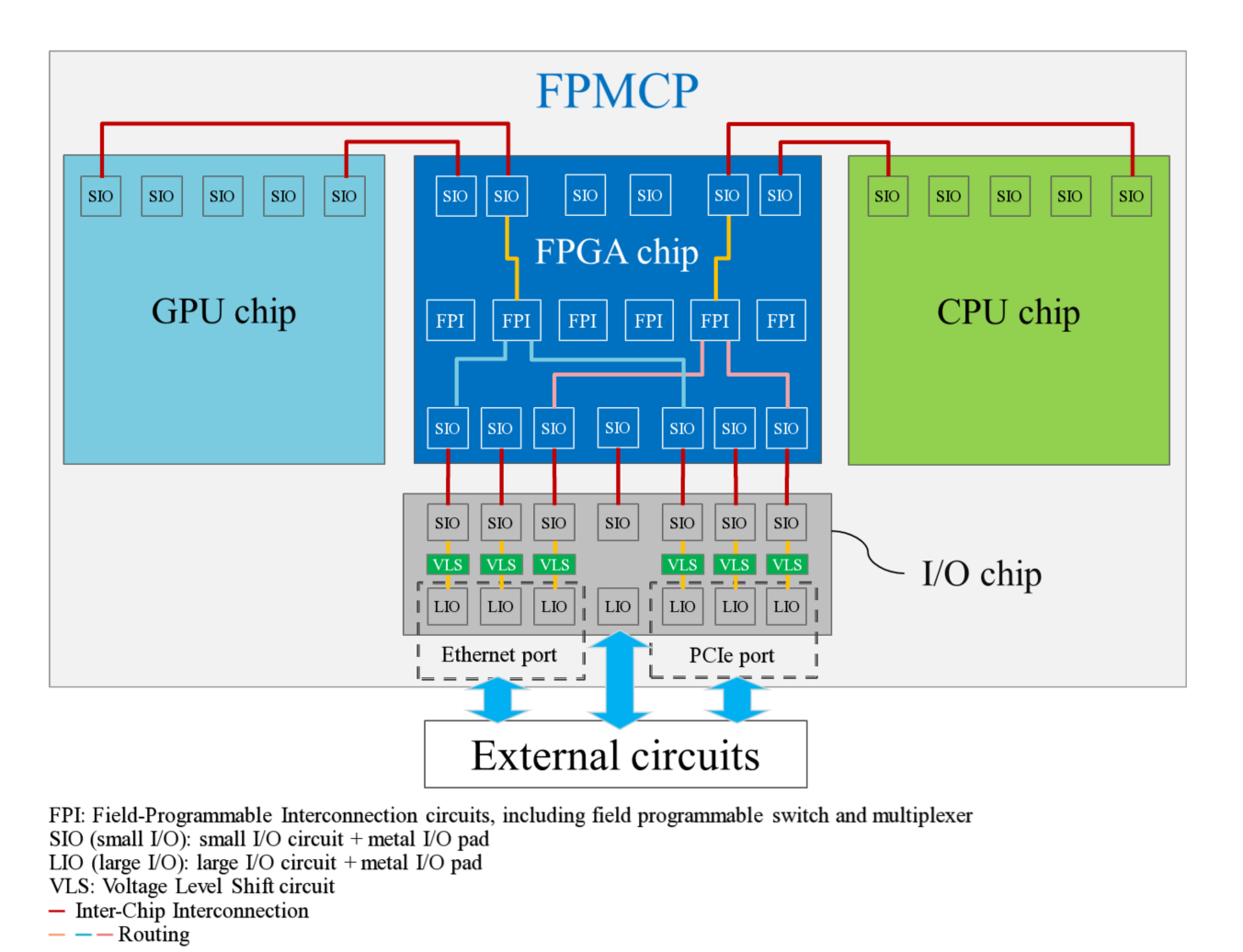
The schematic drawing above further shows the I/O chip comprises large I/O circuits, small I/O circuits and transfer circuits (for example, Voltage Level Shift circuits). The I/O chip couples to the external circuits using large I/O circuits and couples to the FPGA chip using small I/O circuits. The transfer circuit adjusts the voltage level of the signal transferring between the large I/O circuit and the small I/O circuit. The large I/O circuits have large driving capability to drive a capacitive load larger than 1 or 2 pF and operate at a higher voltage (for example, higher than 1 or 2 volts), while the small I/O circuits have small driving capability to drive a capacitive load smaller than 1 or 0.5 pF and operate at lower voltage (for example, lower than 1 or 0.7 volts).
Through the field-programmable feature of the FPGA chip, the function of the expensive computing chips (such as CPU, GPU, ASIC, SOC) in the FPMCP could be changed or upgraded for specific applications, even at a time when the wafer processes are finished. The FPMCP is changed for, for example, the upgrade of communications protocol, the customization of computing algorithms, the renewal of hardware, or the encryption for security. When a new application emerges, a speedy response to the market could be achieved by re-configuring the FPGA chip in the FPMCP within a short period of time. There is no need to re-design/re-build new chips, therefore, results in big cost saving.
Taking the development of Artificial Intelligence (AI) as an example, the algorithm of learning or inference would be optimized continuously based on the accumulated results. The algorithm built on the FPGA chip could be upgraded by reconfiguring the hardware circuits of the FPGA chip through software programming. The FPMCP with FPGA chip in it provides great flexibility during the development of AI.
(B) Use the FPGA chip for cooperating computation with the other computing chips in the FPMCP to accelerate the computing speed of these chips.
Utilizing the unique feature of Software-Defined-Hardware of FPGA, the FPGA chip could generate hardware circuits for specific computing purpose by software programming, and then cooperate with the other computing chips in FPMCP in executing computing processes. The FPGA could greatly accelerate the computing speed of these chips. The schematic drawing below shows how the FPGA chip accelerates the CPU in executing computing job.
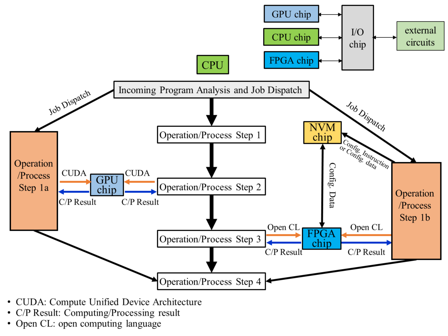
In the FPMCP, the cooperating computation procedures between FPGA chip, CPU chip and GPU chip are described below:
(1) When receiving a job, the CPU analyzes the job instructions, informs and dispatches the GPU chip for the preparation of processing Operation/Process step 2 and the FPGA chip for the preparation of processing Operation/Process step 3. The CPU chip either (a) sends a verified and debugged set of configuration data or information to the FPGA chip through the NVM chip to configuring the FPGA chip, or (b) sends an instruction to select one of a plurality of configuration data or information sets stored in the NVM chip to configuring the FPGA chip; in which each of the plurality of configuration data or information sets is verified and debugged.
(2) When the CPU chip completes the Operation/Process step 1 and go to Operation/Process step 2, it delivers an instruction to the GPU chip through CUDA (Compute Unified Device Architecture) for executing the assigned job. The GPU chip then returns the computing/processing results (C/P results) back to CPU chip after finishing the job.
(3) The CPU chip receives the computing/processing results from the GPU chip and treats them as an input data for Operation/Process step 3. The CPU chip then sends instructions to the configured FPGA chip through Open CL (Open Computing Language) for corresponding operation. The configured FPGA chip sends the computing/processing results back to CPU chip after finishing the assigned operation.
(4) The CPU chip receives the computing/processing results from the FPGA chip and treats them as an input data for the Operation/Process step 4, continues the Operation/Process step 4, and then completes the whole job.
(II) The NVM chip turns the FPMCP into the non-volatile FPMCP
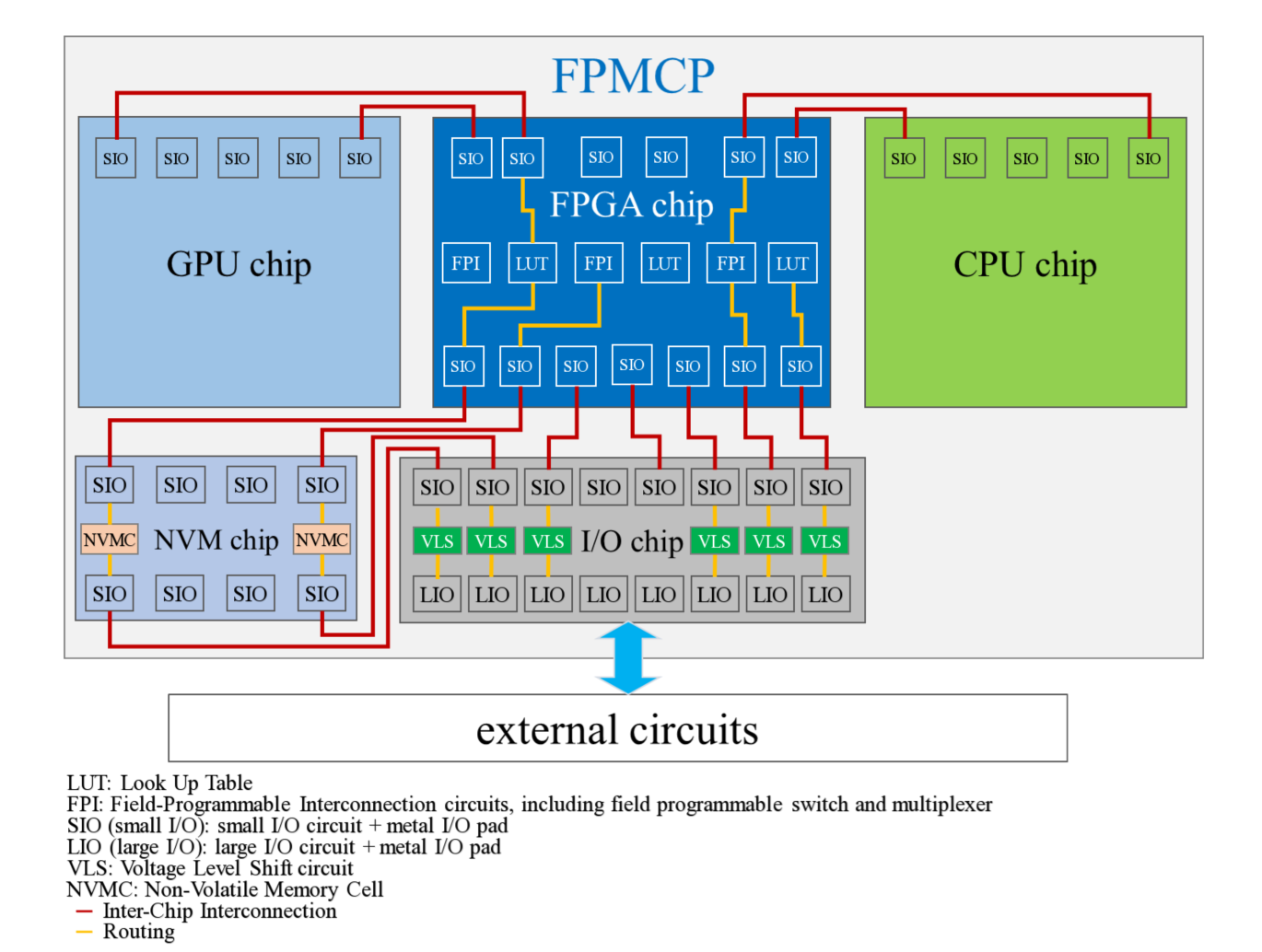
The configuration data for the FPGA chip or chips in the FPMCP is stored in the non-volatile memory cells of the NVM chip packaged in the same FPMCP. The FPMCP is now becoming a non-volatile FPMCP. In the FPMCP, the NVM chip couples to the external circuits and to the FPGA chip in three different methods depending on that the NVM chip is a standard commodity NVM chip available in the market, or is designed specifically for the FPMCP.
(i) The NVM chip is a standard commodity NVM chip (comprising large I/Os only)
The standard commodity NVM chip comprises large I/Os only, therefore, the NVM chip couples to the external circuits with the on-chip large I/Os, and couples to the FPGA chip through the I/O chip for transferring the configuration data.
The coupling between the standard commodity NVM chip, FPGA chip and I/O chip are described below:
(a) A large I/O on the NVM chip couples to a large I/O on the I/O chip.
(b) A transfer circuit on the I/O chip receives signal, data or information with a higher voltage from the large I/O on the I/O chip, and turns them into signal, data, or information with a lower voltage for a small I/O on the I/O chip; or a transfer circuit on the I/O chip receives signal, data or information with a lower voltage from a small I/O on the I/O chip, and turns them into signal, data, or information with a higher voltage for the large I/O on the I/O chip.
(c) The small I/O on the I/O chip couples to a small I/O on the FPGA chip.
(ii) The NVM chip is designed specifically for the FPMCP (comprising small I/Os only)
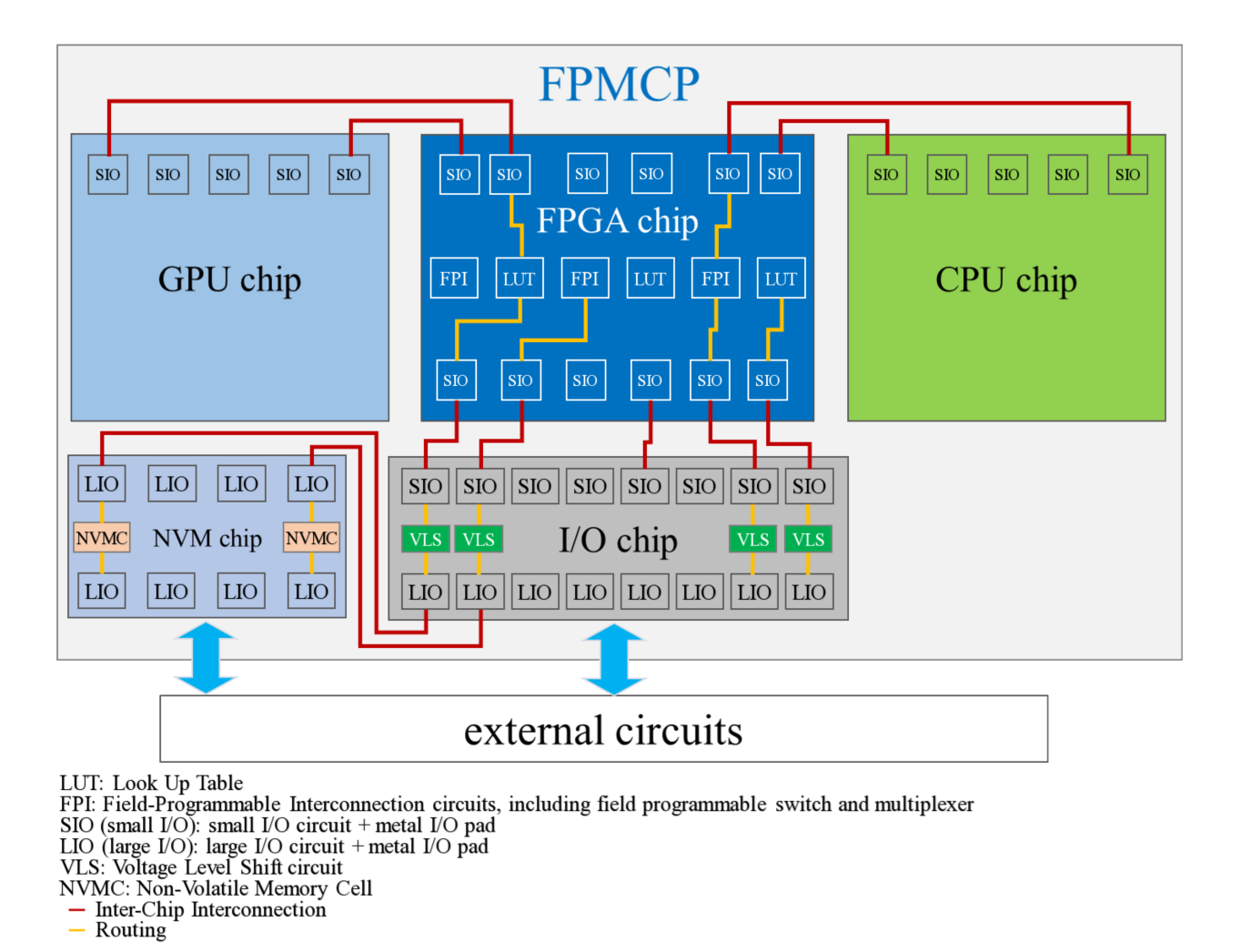
The NVM chip is designed specifically for the FPMCP and comprises small I/Os only, therefore, the NVM chip couples to the FPGA chip with the on-chip small I/O for transferring the configuration data, and couples to the external circuits through the I/O chip.
The coupling between NVM chip, FPGA chip and I/O chip are described below:
(a) A small I/O on the FPGA chip couples to a small I/O on the NVM chip.
(b) The small I/O on the NVM chip couples to a small I/O on the I/O chip.
(c) A transfer circuit on the I/O chip receives signal, data or information with a higher voltage from the large I/O on the I/O chip, and turns them into signal, data, or information with a lower voltage for a small I/O on the I/O chip; or a transfer circuit on the I/O chip receives signal, data or information with a lower voltage from a small I/O on the I/O chip, and turns them into signal, data, or information with a higher voltage for the large I/O on the I/O chip.
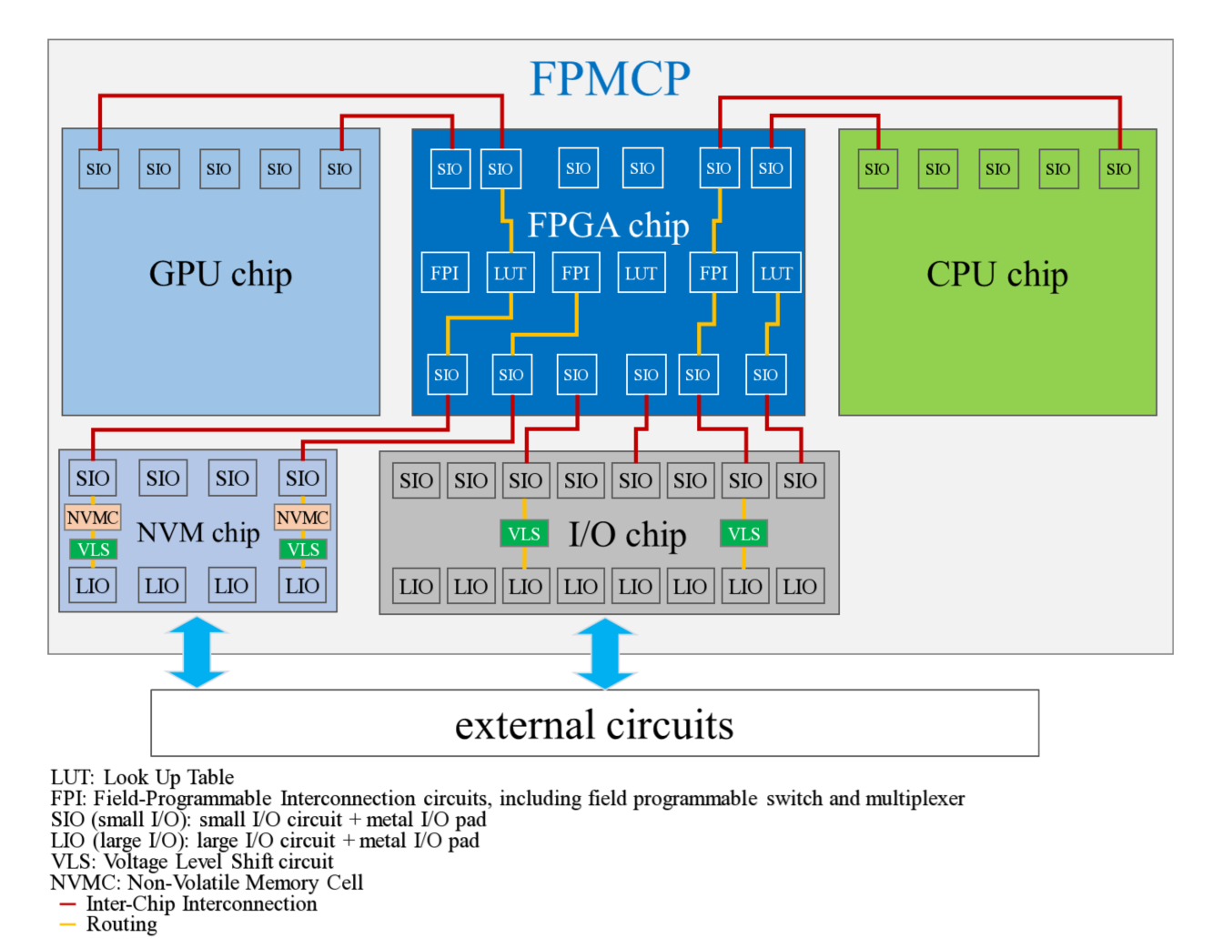
(iii) The NVM chip is designed specifically for the FPMCP (comprising large I/Os and small I/Os)
The NVM chip comprises large I/Os and small I/Os. The NVM chip couples to the external circuits with large I/Os, and couples to the FPGA chip with small I/Os for transferring the configuration data.
(III) The advanced multichip packages for the use of FPMCP
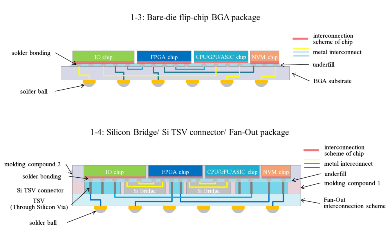
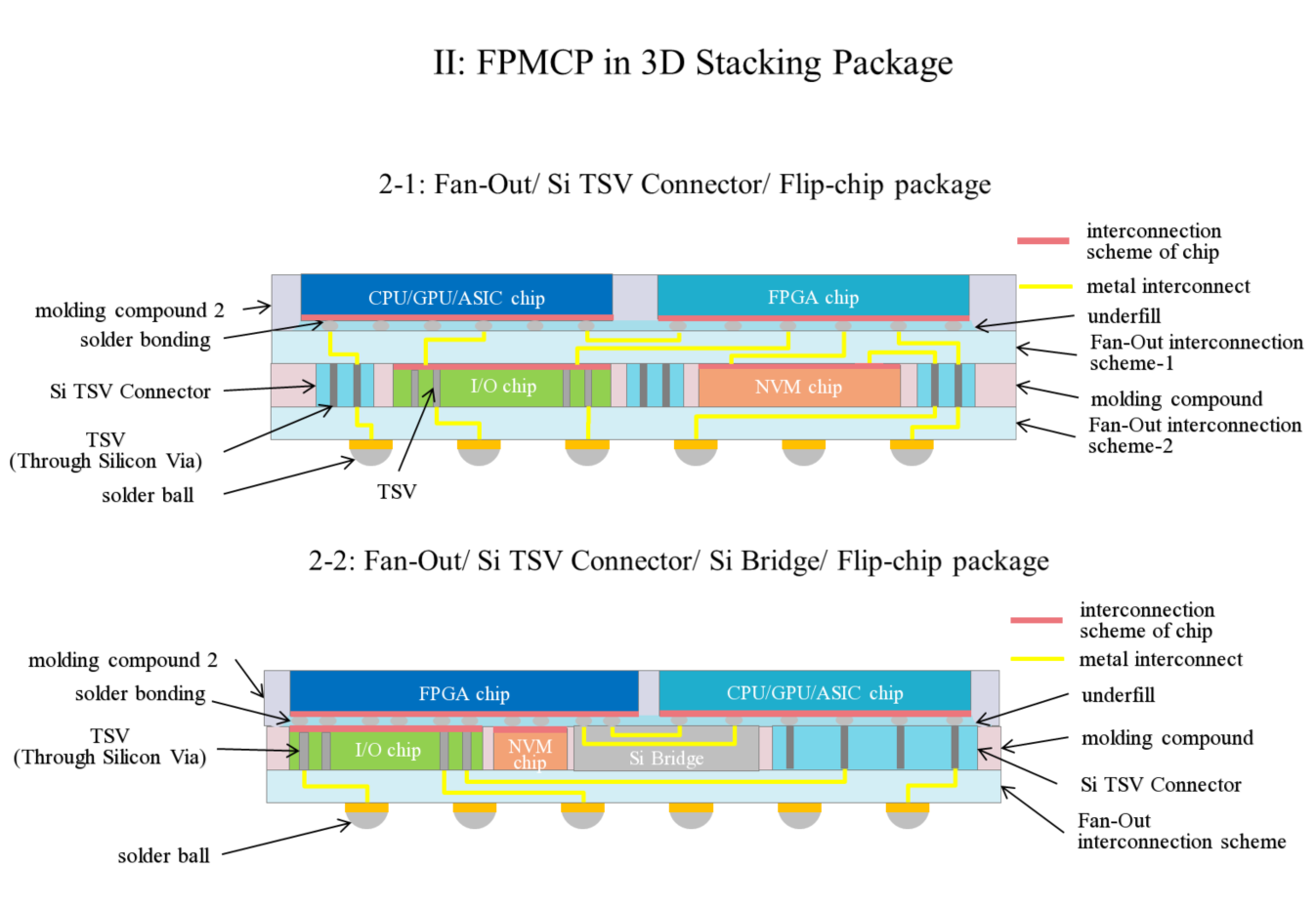
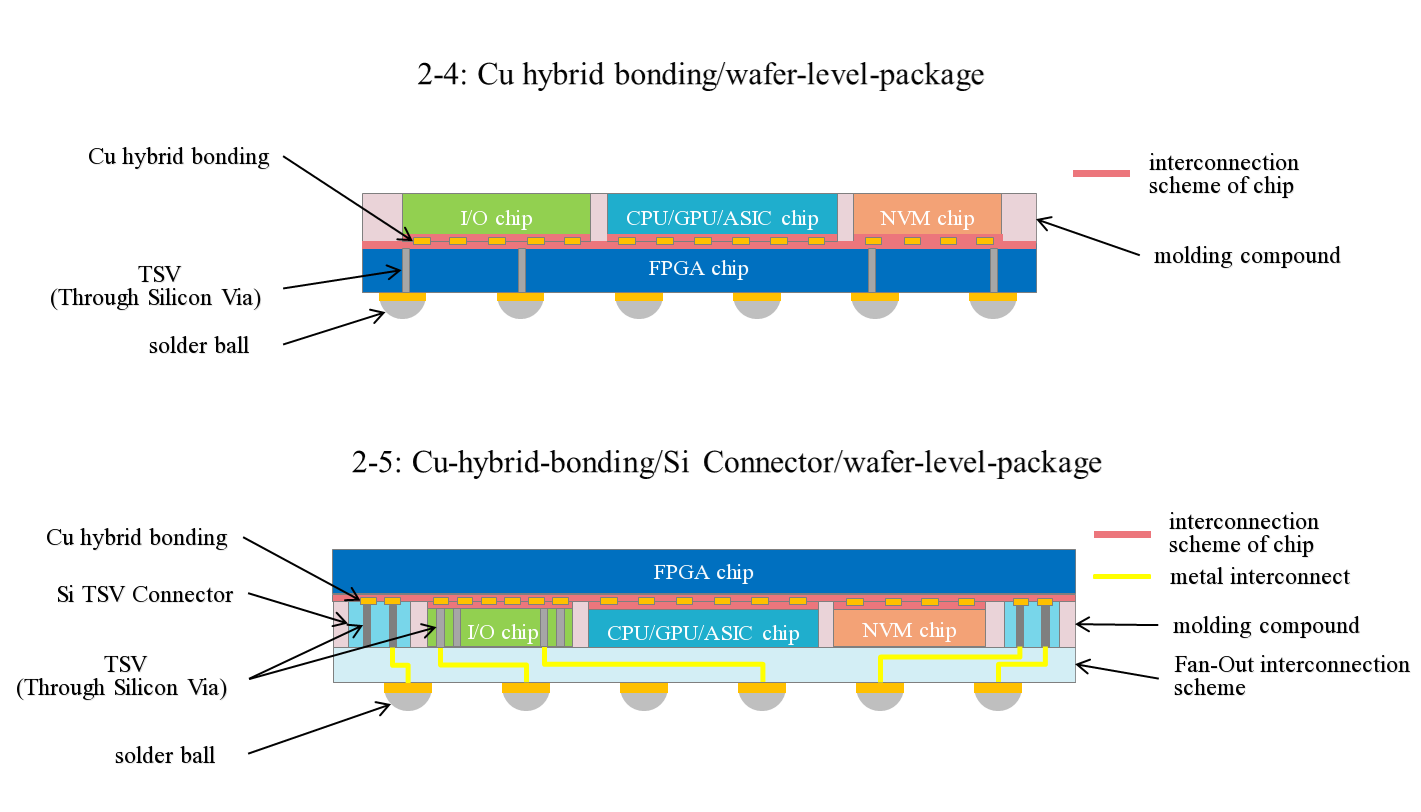
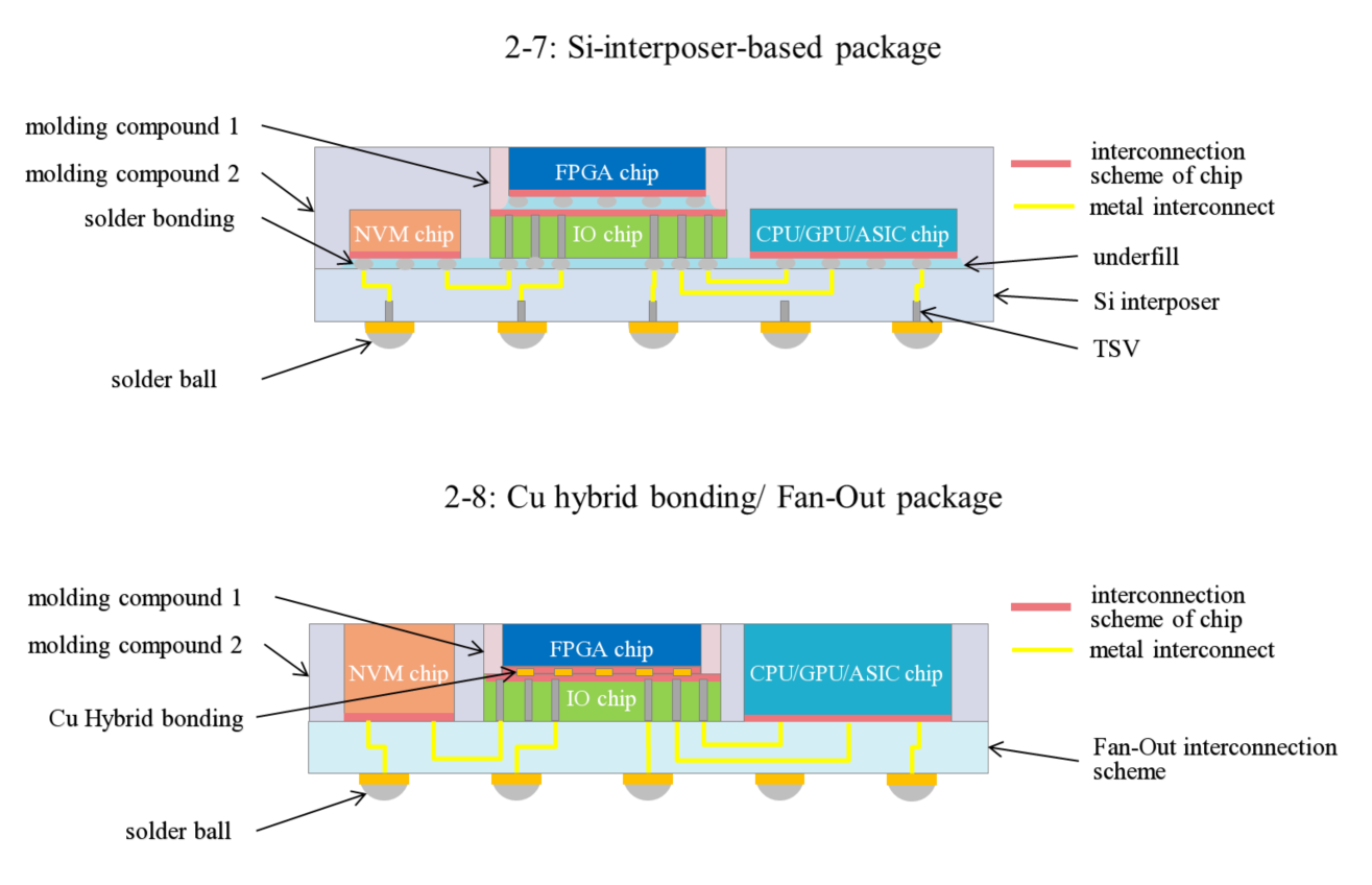
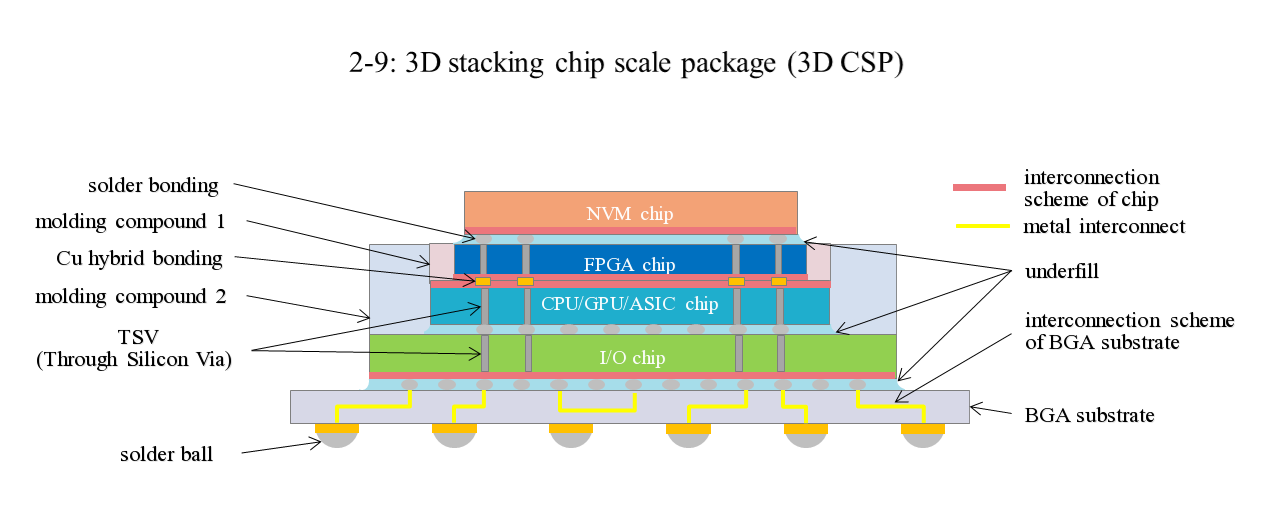
The FPMCP mentioned above are fabricated by using advanced multi-chip packaging technologies to form 2D planar package or 3D stacking package. A variety of advanced multi-chip package structure used for FPMCP are shown below. The schematic drawings below further show the interconnections between FPGA, CPU/GPU/ASIC, NVM and I/O chips. The interconnection between NVM, FPGA and I/O chips shown in all the figures are only for the case that the NVM chip comprises large I/Os and small I/Os (method (iii)) mentioned above; while the cases comprising large I/Os only (method (i)) or small I/Os only (method (ii)) are not shown, and the interconnection methods (i) and (ii) between FPGA, CPU/GPU/ASIC, NVM and I/O chips are as well applied in all the packages shown in all figures below.
